When looking at most board games the main two parts are the board and the game pieces, electronics are rare. However if included, especially in a clever way, they can offer something very unique to your game. In this task you have the choice of using LED's (lights), motors and buzzers. These will allow your game to have sound, light and movement. As with the board and the game pieces, the electronics for this part of the task can be designed in Tinkercad. It is important that you first build the idea of your game in Tinkercad so that you can work out how you need to connect your parts. Very careful planning for this part will save you a lot of work fixing it later on. The file I used to create the electronics is below as is a link to the example of a build journal, something you will need to keep as you progress through the build.
|
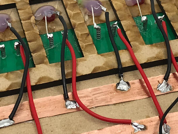
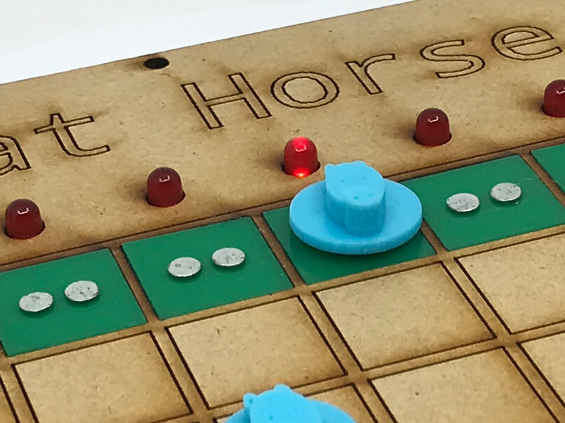
To make your game pieces work as switches you will nee a conductive bottom circuit on your game pieces and also some electrical connections on the board, you will need to make sure you are working with the other members in your group to make sure this has been considered in their design. Some examples of how this may look when connected on a real game are shown opposite and at the top of the page
The copper tape as seen at the top of the page is a good way of creating a common rail for things to be connected to. |
|
|
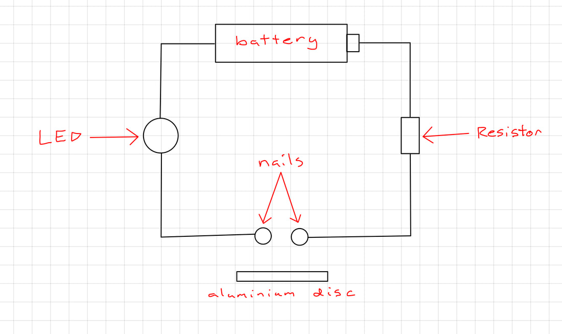
When using the game pieces to trigger electrical events in your game it is important to understand how the nails work. A basic diagram of it is shown. Essentially if there is a wire attached to each nail, and the nails are not touching, then then this essentially acts as a break and in the wire and therefore the light does not turn on. However by adding the aluminium disc you are rejoining that wire, as electricity flows through the nail, into the disc and then through the other nail, which allows it to turn on.
The resistor is in the circuit to regulate the flow of electrical current, this is to protect the LED so it doesn't burn out. |
|
|
For many of you, this will be your first experience with soldering an electronic circuit. If the electronics are your part of this task then your teacher will run through some of the basics of soldering with you. However there is also a video refresher opposite.
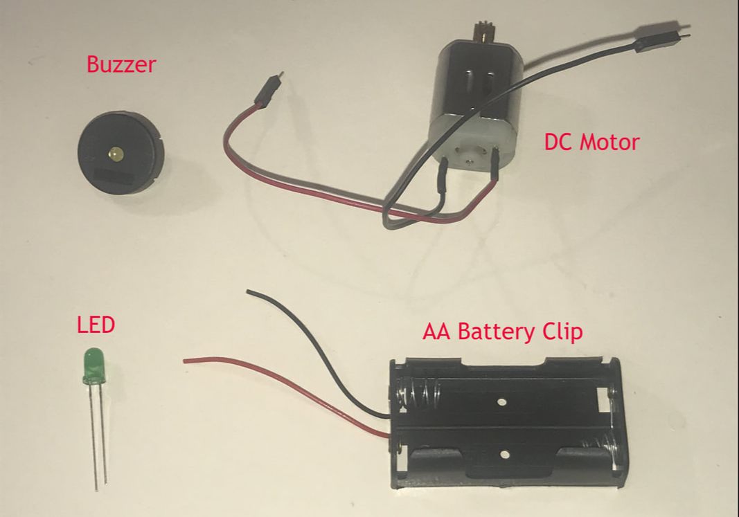
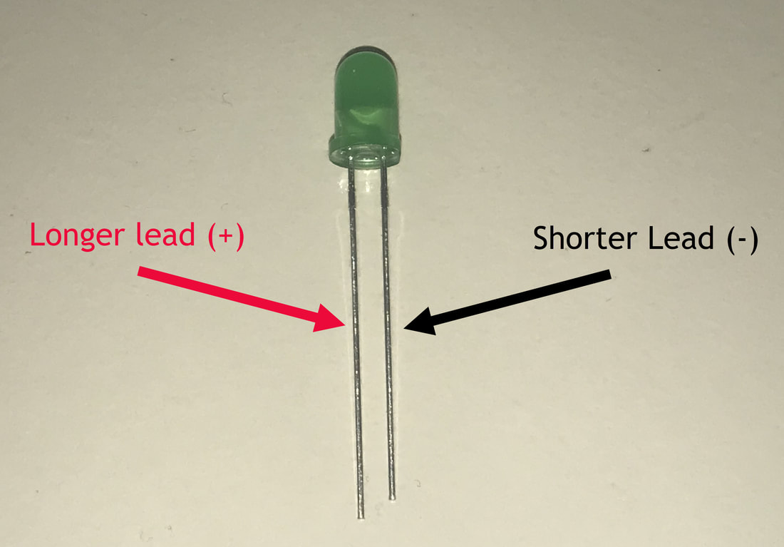
Below are some of the electrical components you will have available for your game, in general if there is a red and black wire the red will be positive (+) and the black negative (-). For LED's this can be trickier, however one lead is often shorter than the other, that short one is the negative lead. Where you have these coloured leads these should be connected to the correct terminal of the batteries. |
|
|
|
