Introduction
|
The technology task for STEMIE is quite diverse in the skill set required to complete the task. There are two main aspects to the tasks Arduino and 3D printing.
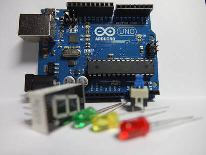
Arduino is a microcontroller that can be used to detect inputs using a range of different sensors, and then respond to those inputs with a range of different outputs such as lights, motors, displays, speakers etc. In learning Arduino you learn to put a circuit together and then program it in order to define how to use the information from your inputs and what to do as an output as a response. Putting a project together is often easier than it looks as there is a lot of different projects, wiring diagrams and code online that you can pick up and use. Often the trickiest part is getting the structure right so it operates as you hope it would. Some examples of previous builds are in the other resources below. |
|
|
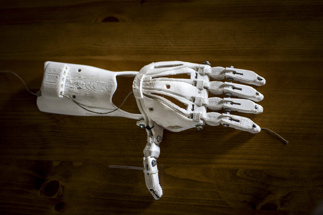
The other part of this section is the requirement for a 3D printed component to your design. These can be passive features in your design such a case for your Arduino, or can play a more active role in your design such as a custom part to add to a motor to complete a task.
There is a range of different types of design software that you can use to design your 3D printed parts. Tinkercad is a simple piece of design software that uses differently shaped blocks to create your models. These blocks can be added to create more complex shapes, or subtracted to remove material for the purpose of making holes or pockets. For more complex parts, Fusion 360 is a good option. It works by a process known as sketch and extrude. In essence it involves drawing your design in 2D (sketch) and then giving that 2D sketch thickness (extrude). Both modelling programs are free for you to use and you can even move your designs between each program. |
Assessment
In this unit of work you will make the choice on whether you are using the technology or the engineering tasks to complete the tasks listed below. You do not need to do this for both tasks.
|
Collaborative Inquiry
|
The collaborative inquiry has two parts, the design, and the evaluation.
Collaborative Inquiry Design In this task you will collaborate to design and conduct a scientific/engineering investigation related to the focus of the STEMIE program in which the outcome is uncertain. In this case it will be based on the development of an innovative prototype to solve a real-world problem. You will individually record your work on, and critical thinking about, this task in a personal journal . The journal should include, but is not limited to:
This personal journal must have a maximum length of 8 pages. Collaborative Inquiry Evaluation In this part of the task you will individually evaluate the collaborative inquiry, in the style of a recorded pitch, defence, or justification. This evaluation should include:
The recorded pitch, defence, or justification should be a maximum of 3 minutes per student if oral or the equivalent if multimodal. |
Other Information
|
The Arduino Get Started website is a good one for getting some ideas for how to wire your circuit and write the code to control your Arduino. It is well organised, so it is easy to find what you want, and you can often build complex projects by splicing together the code and wiring from different projects.
|
|
In this task students were required to create an entry system for a carnival to accurately keep track of the number of people in attendance. In this case it involved a push button for entry that raised the boom gate and added 1 to the counter before closing the boom gate. and a second button for exit that reversed the process by raising the boom gate, taking 1 off the counter and then lowering the boom gate. A more advanced version of this would include a sensor rather than a button.
|
|
|
In this project students had to design a system to deal with flood water. In this case as the rising water caused the arm to float it turned a sensor. Below dangerous levels the LED would display green. At a certain amount of turn it would give some warning beeps and turn the yellow LED on instead, and finally when the water got to a dangerous level it would go to red, beep much louder and open the flood gate to release some water. As the water level drops it returns back to normal levels and the warnings stop occuring.
|
|
